Mastering the art of MIG welding requires one crucial element: learning how to optimize MIG welding gas pressure. Shielding gas plays a key role in protecting the welding arc and the molten weld pool from atmospheric air and other impurities, ensuring the formation of high-quality welds.
MIG Welding Shielding Gas Pressure
Welding Town
Yet, setting the right pressure proves to be complex. A lower flow rate shielding gas results in poor shielding gas coverage, causing poor weld quality. On the other hand, excessively high gas flow also brings complications. So, what is the solution?
In this article, we will explore how to optimize gas pressure for MIG welding, guiding you toward achieving flawless welding results.
Role of Shielding Gas in MIG Welding
Shielding gas’s primary function is to protect the active weld pool from interacting with external elements in the surrounding environment, preventing contamination from oxygen, hydrogen, and nitrogen, typically found in the atmosphere. If allowed to come into contact with the molten metal, these gases can lead to weld defects such as porosity, cracks, etc.
Therefore, ensuring proper use and flow of shielding gas is not just important; it is crucial for achieving strong, visually acceptable, and sound welds. An insufficient quantity or inappropriate shielding gas selection could risk the weldment’s quality and integrity.
Commonly Used Shielding Gases in MIG Welding
The common shielding gases used in MIG Welding are:
- Argon
- Helium
- Carbon dioxide and
- Oxygen.
Argon
When the MIG welding objective is quality and visually good weld bead, and minimum post-weld cleaning, a mix of 75% argon and 25% carbon dioxide (or 75 to 95% argon and 5 to 25% carbon dioxide) can be a good choice.
This shielding gas allows a stable arc, low spatter, and control over molten weld puddles. However, this mix is suitable for welding mild steel and alloy steels but not for stainless steel and aluminum.
The recommended shielding gas for MIG welding stainless steel is pure argon or a mix of argon and helium. Sometimes a small percentage of carbon dioxide (2 to 2.5%) is added to make a tri-mix shielding gas (argon, helium, and carbon dioxide).
The shielding gas used for welding aluminum is 100% argon or a mix of argon and helium.
Helium
Helium is an inert gas (like argon) mixed with argon for MIG welding aluminum and stainless steel. It has good thermal conductivity and helps improve weld penetration. The percentage of helium added to argon can range from 25 % to 75%.
The density of helium is lower than argon. Hence it affects the required flow rate of shielding gas. The higher the helium percentage, the higher the shielding gas flow rate needed. With stainless steels, Helium is typically used in a tri-mix formula of argon and CO2 gas.
Carbon Dioxide (CO2)
Carbon dioxide is an active/reactive gas, the only gas that can be used 100% (without adding inert gas). This is the cheapest shielding gas, provides deeper weld penetration, and is highly useful for welding thick material.
However, using 100% carbon dioxide has problems like an unstable welding arc, high spatter, and other issues. Because of this, carbon dioxide is normally mixed with an inert gas for MIG welding, and the popular mix is 75% argon and 25% carbon dioxide.
Oxygen
Oxygen is a reactive gas added in very small ratios in the shielding gas mix for improving weld penetration and arc stability for MIG welding steel and stainless steel.
The presence of oxygen in the shielding gas can cause a layer of oxidation, and hence it is not recommended for aluminum and similar metals.
MIG Welding Gas Pressure Setting
To choose the right gas pressure for MIG welding, you must first determine the type of material you’re welding. The pressure and flow rate of the shielding gas is important for good MIG welding.
If you connect a pressure gauge on the shielding gas hose, you will observe that the pressure of the shielding gas in the hose increases with the increased flow rate of the gas.
A higher or lower gas pressure can waste gas and lead to an inferior weld start. It is important to follow the recommendations for welding gas pressure.
Unlike in some welding processes (like oxy-fuel welding), where the delivery of the gas is monitored by varying its pressure, the delivery pressure of the shielding gas in MIG welding is comparatively very low.
When setting the gas pressure on a MIG welder, it is important to know the CFH (Cubic feet per hour) of the gas. And it is simple and easy to monitor the delivery of the shielding gas by its flow rate (CFH) instead of delivery pressure (PSI or pounds per square inch). Hence, the MIG gas regulator’s gauge on the delivery side is calibrated in CFH.
Shielding Gas Flow Rate Chart
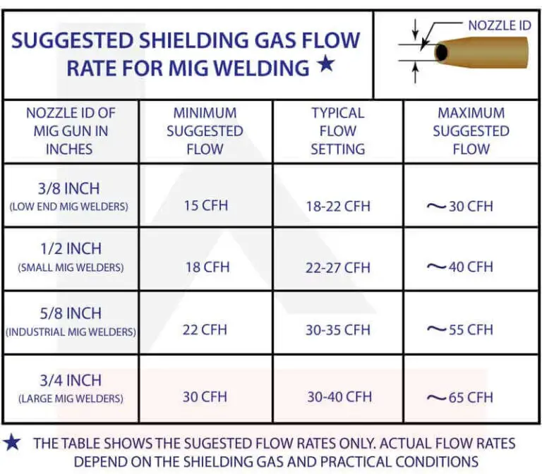
The shielding gas flow rate chart shows the minimum and maximum flow rate for each nozzle size, and the flow rate should not exceed the maximum limit.
The suggested flow rate in the chart is the estimated rate. The actual flow rate will vary according to the welding location, type of weld joint, welding position, base metal thickness, size of filler wire, and welding speed (the optimum flow rate of the shielding gas comes from a little trial and error). Your MIG machine may have charts for the recommended gas flow rate.
The following table shows the recommended gas flow rate based on MIG welder nozzle size. Remember, this is just a high-level recommendation. The actual flow rates will depend on the shielding gas type, joint configuration and welding conditions.

The nozzle size (inside diameter) that are used on a small MIG welding machine are 3/8ʺ and 1/2ʺ, a 5/8ʺ nozzle is used on industrial MIG welders, and the large size of 3/4ʺ is used on large MIG machines that use higher diameter cored wire. The higher-size nozzle allows you to do MIG welding faster with a higher CFH of shielding gas.
Factors to Consider When Optimizing Gas Pressure in MIG Welding
- The location of welding (indoors or outdoors) and the prevailing airflow.
- The type of weld joint
- Welding speed
- Type of shielding gas
- Type of base metal and its thickness.
Location of Welding
If you are welding indoors, the influence of the blowing wind is less, and you can use a lower flow rate of shielding gas. On the other hand, if you are welding outdoors, the wind’s influence is greater, and you need a higher flow rate of shielding gas to overcome the blowing wind.
You can minimize the influence of the blowing wind by using protection shields around the job. Thus, you can optimize the flow rate of shielding gas by doing MIG welding indoors whenever possible, and when it is necessary to do it outdoors, use protection shields around the job.
The Type of Weld Joint
The type of weld joint also has little influence on the required flow rate of the shielding gas. If you are welding flat base metal surfaces (butt welds), the shielding gas from the nozzle spreads faster, so a higher flow rate of shielding gas is required.
On the other hand, fillet welds require less shielding gas flow rate since the vertical member of the weld joint provides a shield from the draft. Hence, the flow rate of the shielding gas for a fillet weld can be a bit less compared to a butt welded joint. Take advantage of the type of weld joint to optimize the gas flow rate.
Type of Shielding Gas
If you study the density of the shielding gasses, you will notice that the density of argon and carbon dioxide are nearly equal. Still, the density of helium is much lower than argon or carbon dioxide. So, if the mix of shielding gas contains helium, it influences the required flow rate of the shielding gas.
You can optimize shielding gas costs by selecting a gas that improves productivity. Using pure carbon dioxide or a mix of shielding gas containing a maximum percentage of carbon dioxide can increase weld penetration and enable a faster welding rate, especially for thicker base metals.
However, this increased productivity comes with certain cons, such as unstable welding arc, higher spatter, and other issues. Too much spatter can block the nozzle opening partially, which affects the flow of shielding gas and may also lead to pressure building up in the hose.
You need to consider the cost of different shielding gasses and use it to optimize the cost of shielding gas. Considering the available options, carbon dioxide, argon, and helium, carbon dioxide is the cheapest gas, helium is the costliest gas, and the cost of argon lies between carbon dioxide and argon.
Type and Thickness of Base Metal
The filler wire size, wire travel speed, and welding speed depend on the type of base metals being welded and their thickness. All these factors influence the shielding gas and its flow rate.
The width of the weld bead is narrow when welding thinner base metals, and the width is more for thicker base metals. You need a lower flow rate of shielding gas to shield narrow weld beads (thinner base metals) and a higher flow rate for wider weld beads (thicker base metals).
When you increase the welding speed, increase the gas flow rate also. The ideal gas pressure range for MIG welding is three to eight PSI (3~8 PSI).
Considering all the above factors, experienced and expert MIG welders have suggested a thumb rule of the minimum flow rate of shielding gas for low carbon steel as 10/15 CFH. It can be 15 or 20 CFH (when welding indoors) for aluminum and stainless steel.
However, the welder has to keep watching the weld bead during welding and increase the flow rate to avoid welding defects.
You need to remember the desired properties of the weld. If you want a good-looking weld bead with very low spatter and minimum post-weld cleaning, the preferred shielding gas is argon or a mix of argon and helium.
Frequently Asked Questions
What happens if we set a very low or very high flow rate of shielding gas in MIG welding?
You should know that too little shielding gas can cause porosity and other problems like cracks; the solution is not turning the flow rate to maximum. A higher flow rate of shielding gas can cause turbulence and allow air to mix into it, eventually affecting the protection of the weld pool.
Hence, getting an optimum flow rate for shielding gas requires trial and error. You can store these data for future use.
What is the shielding gas and flow rate required for MIG welding Stainless steel, Aluminum, and Carbon steel?
MIG Welding Stainless Steel
Stainless steel is not easy to weld due to its low thermal conductivity.
The recommended shielding gas for MIG welding stainless steel is pure argon or a mix of argon and helium. Sometimes a small percentage of carbon dioxide (2 to 2.5%) is added to make a tri-mix shielding gas (Argon, Helium, and Carbon dioxide).
Helium conducts heat fast, but stainless steel has poor thermal conductivity. Helium mix gas needs a higher CFH due to the low density of helium. So, starting with 20 to 25 CFH can be good. And the flow rate can be increased if you observe bead porosity.
MIG Welding Aluminum
Unlike stainless steel, aluminum has good thermal conductivity. Also, you can go for a higher wire travel speed and a higher welding rate. A higher rate of welding needs a higher CFH of shielding gas.
The recommended shielding gas for aluminum is 100% argon or a mix of argon and helium. Depending on the shielding gas composition, the flow rate required may be 30 to 50 CFH.
MIG Welding Mild and Low Carbon Steel
A mix of argon and carbon dioxide (75% argon and 25% carbon dioxide) is normally used as the shielding gas for MIG welding mild and low-carbon steel. And the shielding gas flow rate can be 10 to 15 CFH.
However, if you notice a porous weld bead, increase the flow rate to the recommended range of 22 to 27 CFH.
How to set the shielding gas cylinder with the gas regulator?
Fasten the shielding gas cylinder to the MIG welding trolley securely.
The valve on the gas cylinder has a knob. You can open the valve by turning the knob in the counterclockwise direction and close the valve by turning the knob in the clockwise direction. Opening the valve releases the gas into the gas regulator.
Open and close the gas cylinder valve two or three times to blow out any particles or dust from its brass connector. Connect the gas regulator to the gas cylinder.
You can find two gauges on the gas regulator; one gauge reads the pressure of the shielding gas in the cylinder (in PSI), and the other gauge is calibrated in CFH (cubic feet per hour) and not PSI.
Watch the following video to be clear about the above steps.
In this video: Jeff talks about how to transport, secure, and hook up a regulator to a high-pressure gas cylinder. He also covers some basic things you need to do to care for your regulators and keep them in good condition and in good working order. Darkmoon Metals is a home-based business start-up, I have decided to live my dream and work for myself. (not like anyone is hiring at the moment) I am a trained welder with a strong interest in blacksmithing, join me for my ups and downs while I learn as I go. Trying to forge a new life in a dead economy that has left many blue-collar people just trying to survive. Music provided by:(User agreement per www.audionautix.com) All music in this online collection was created by Jason Shaw. Released under Creative Commons license 3.0 You are free to use the music (even for commercial purposes) as long as you credit “audionautix.com” where possible. Music must be part of some other created works. No further permission is required.
Adjusting the flow of the shielding gas is not a difficult task
Open the valve of the gas cylinder, and open the valve of the gas regulator to allow the flow of gas into the hose.
To know the flow rate of the shielding gas, press the switch on the MIG torch. You will notice the filler wire and gas coming out. And you can read the flow rate on the gas regulator. Adjust the flow rate to the required value using the regulator valves.
Another version of the gas regulator has one gauge for reading the gas pressure in the cylinder. The flow rate in CFH is indicated by a flow meter (this is also called a flow meter regulator).
This flow meter consists of a graduated (graduations in CFH) transparent plastic chamber and a transparent plastic tube. There is a floating steel ball in the plastic tube.
When the shielding gas flows through the flow meter, the gas pressure rises in the steel ball. You can increase gas flow by opening the valve more. And the steel ball rises further to indicate the increased gas flow.
The steel ball comes down if you reduce the gas flow. And this movement of the steel ball gives you visual proof of the flowing gas.
Are gas regulators common for all types of shielding gasses?
| The Density of Shielding Gas | |||
| Name of the gas | Argon | Helium | Carbon dioxide |
| Density in Lb./ft3 | 0.1032 | 0.0103 | 0.1137 |
| Density in Kg/m3 | 1.7572 | 0.1761 | 1.9359 |
The above table shows the density of argon, helium, and Carbon dioxide. And you can observe that the densities of these gasses are different. Because of this, gas regulator/flow meters calibrated for one shielding gas cannot be used for another. This applies to the mix of two or three shielding gasses also.
When buying the gas regulator for shielding gasses (argon, helium, carbon dioxide, or a mix of two or three gasses), confirm the fitting size required before you finalize.
Conclusion
Shielding gas is a significant investment. Therefore, optimizing the pressure and flow rate of the shielding gas contributes to cost savings while ensuring the highest level of protection for your welding arc and molten pool.
Applying the knowledge and techniques discussed in this article, you can confidently approach MIG welding gas pressure optimization. Leading to improved welding results and a more cost-effective process. So, as you continue honing your craft, bear in mind the importance of striking that perfect balance – your work and your wallet.


